


 246 / 308

246
Machine Elements
Calculation of Load Distribution in Complex Gear Systems
Planetary gear sets are widely used in industry and auto-
motive applications. Compared to a basic cylindrical gear
pair, they offer high transmission ratios and high power
densities due to load sharing across several planet gears.
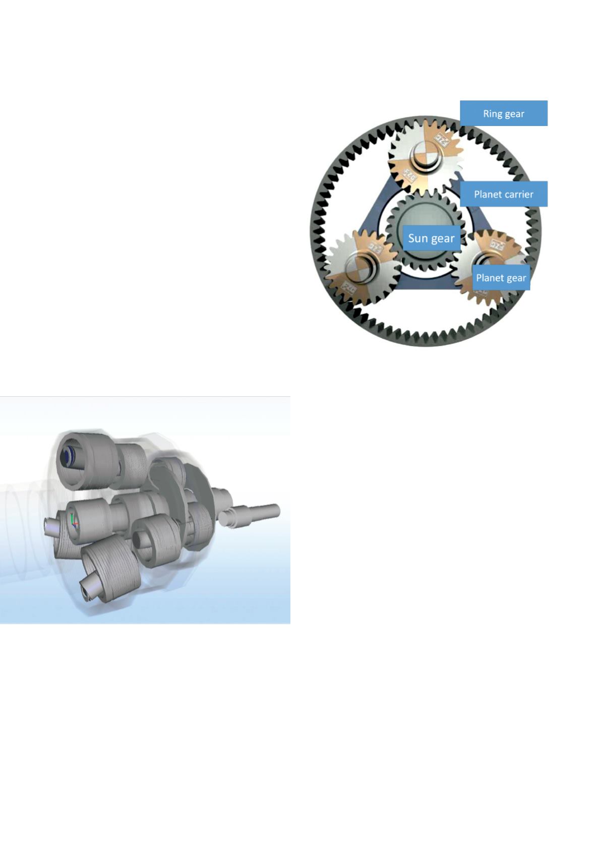
They usually consist of a central sun gear, several plan-
etary gears (orbiting round the sun as well as rotating on
their own axes) and an outer ring gear. The planet gears’
axes are mounted on a planetary carrier, which forms the
third coaxial shaft, in addition to the sun gear’s shaft and
ring gear’s shaft.
When in need for even higher transmission ratios, more
than one planetary gear set can be arranged sequentially,
as was done in the gearbox shown below.
Load-induced deformations and manufacturing or
assembly-related errors influence local peaks of the tooth
load and the load deviation in the meshes of planetary
gear sets. In modern transmission systems, deformations
of transmission elements and associated displacement
of gear wheels in tooth contact can be compensated by
modification of the tooth geometry.
The design of flank modifications in planetary gear
systems is based on the reliable and accurate calculation
of the three-dimensional positons of the central shafts and
the load sharing behavior between the planets. Practical
methods used previously often neglect these influences
and assumed equal load distribution between the planets
and central shafts in non-deflected positions.
With the FZG’s simulation approaches, load distribution,
load sharing behavior between planets and deformation in
arbitrarily coupled planetary gear sets can be calculated
and tooth flank modifications can be designed.
The 3D graphics show the nominal and the deformed
(exaggerated) state of an example multi-stage planetary
gear set from which gear flank load distributions can be
calculated.
Using this elastic deformation analysis, the influence of
different carrier angular positions on the momentary load
distribution of each gear mesh is determined, as shown in
the diagram above (showing mesh load over tooth width
for several carrier positions).
This deformation and load distribution information can
serve as a base for flank micro-geometry modification
design. Applying these micro-geometry modifications in
the manufacturing process allows for a favorable load dis-
tribution during operation. With this at hand, an optimized
load carrying capacity or noise excitation behavior can for
example be achieved.